
Now that you know how to figure out the photometrics for an instrument, you can now apply those photometrics to the architecture of a venue, and the nuances of a set design. We will apply these techniques to a black box space with a pipe grid at 19'-0". We will also experiment with a couple custom trim heights to practice that aspect.
We will start by plotting 4 area lights for this lighting area:
We will start by plotting 4 area lights for this lighting area:
- (1) Top Light,
- (11) Front Light, at a shallow 'front fill' approach angle (30°)
- (21) High Side, coming in at a steep 60° approach angle
- (31) Diagonal front light, using McCandless as our guide- 45° Approach angle and 45° diagonal
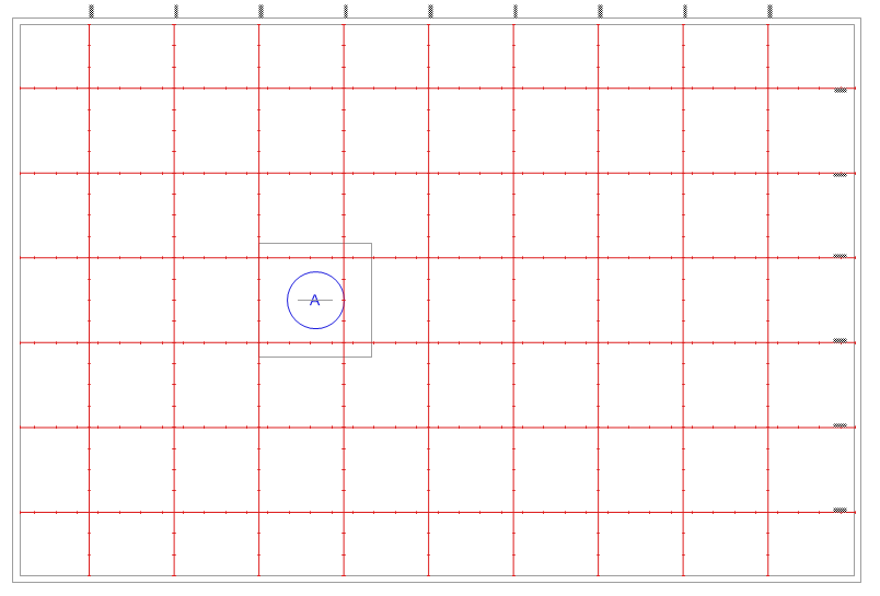
Black Box Plan View
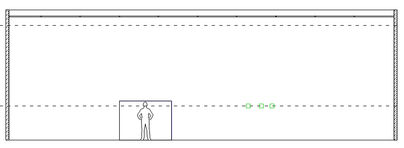
Black Box Section View- Front
|
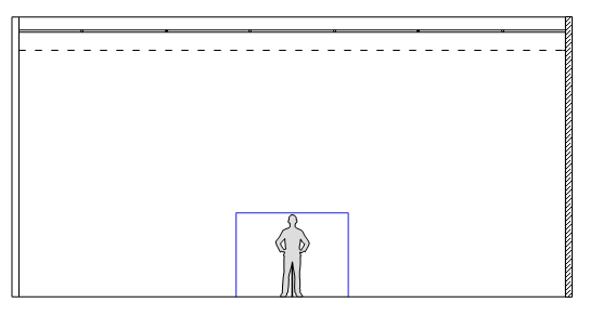
Black Box Section View- Side
|

TOP Channel (1)
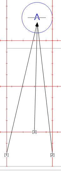
If I have a Top light system in my plot, I almost always plot that first. They're the easiest fixture to plot, because they hang directly above the Focus Area. In this venue, I have pipes everywhere, except right where I need it, so with my first light I need to make my first choice. The three closest spaces that exist for me to hang the light are labeled in this drawing as [1] [2] and [3]. If I hang it at position [2], the light will come in at a slight angle from the point of view of the audience. I really don't like that- I don't want the audience to perceive a directional bias from the top light, so I'm going to eliminate position [2].
[1] and [3] give me two different options. [1] is 'slightly back', and will give me more shadows on faces, and a greater ability to 'halo' actors, creating more sculpting ability. [3], on the other hand may give me additional ability to highlight faces, because while it is an extremely steep angle, it will catch a little more face when the actor is facing the audience. In this case, I will choose [1] for the greater ability to sculpt the shape of the actors on the stage.
Now that I know where the light will hang, I can move on to choose a fixture. First I'll choose between a Wash fixture or a Profile fixture. I don't need any gobos or shutters for this system, so I'm going to choose a Wash fixture. I have some PAR fixtures and some Fresnel fixtures in my inventory, so we will use one of those for this system- but which one? .
|
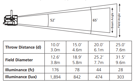
I've measured the beam angle to cover the whole area, and came up with 36°. The photometric data for my PAR units says that the oblong WFL (Wide Flood) lens will give me almost what I need in the long direction (Beam Angle=32°) but in the short direction (Beam Angle=17°), not even the Field Angle will cover the space that I need. These fixtures are probably best used elsewhere.
The Fresnels are better. At full flood, the Beam Angle stretches to 52°, and I don't need near that much, so I know that I'll be able to spot them down somewhat. (The datasheet also gives a medium flood measurement with a Beam Angle of 21° - we'll go halfway between those two points at focus). Comparing the luminance between the two fixtures tells me that I'll get 158fc from the PAR at 20', but only 44fc from the Fresnel, but once we spot in the fixture, the luminance jumps quickly. At Medium Flood (not shown here) the 20' luminance is 120fc. We will end up somewhere between 44 and 120. This system has only a medium saturation color in it, so I think we'll be OK. If we were going with a highly saturated color with a low tranmission factor, I might go to the brighter PAR fixture. |

|

What the audience sees from the different top light placement choices
|

A side view of our two remaining choices
|

Measurement of the beam angle from the chosen position
|

The reasons for making these choices are always tied to the play itself. In three different plays, given these three choices I might make a different decision every time. We eliminated [2] because I didn't want the slight directional bias, but truly, that position gives us the steepest, and truest 'top light' angle, so it might be the right choice for another show. I went with [1] over [3] in order to get better sculpting and halo effect, but if the play is a comedy and I want to maximize light for facial expressions, [3] might be the better choice. And in some cases, I might decide that it's really important to have that true top light, directly above the center of the focus area, and I want to spend resources in order to attach an auxiliary pipe to the grid so that I can have a hanging position right where I want it.
This is a great example of the decision making process that you make for every system and every fixture.
Congratulations- we've plotted one fixture! (Don't worry- it gets easier from here)
This is a great example of the decision making process that you make for every system and every fixture.
Congratulations- we've plotted one fixture! (Don't worry- it gets easier from here)
FRONT LIGHT: Channel (21)
This system is intended to be a shallow approach angle so that we can fill in the faces, perhaps for a TV broadcast. In most cases in the theatre, I would not use a system like this for my primary visibility, but a light coming from a 'balcony rail' position (so named because it is a pipe hanging on the front face of the balcony in a traditional auditorium) is a common position in many theatre venues.
In this case, we're going to aim towards a 30° Approach Angle. I've also heard some designers (especially coming from the TV side of the business) advocate for a 22.5° Approach Angle. Let's first look at the Section to determine our Plot Distance. Striking a 30° line out from the focus area unfortunately gives us a fixture placement on the other side of the theatre wall! No good. So we need to go over our options again. If I push the fixture just inside the theatre wall, the Approach Angle only changes to 34° from 30°, so that's not too big of a difference, but if I look at the groundplan, I notice that I would need to place the fixture on the end of a 'north/south' pipe', and there is not one right in line with my focus point. This means I would need to come in at a slight angle again [1] and [2]. Because I'm trying to eliminate shadows as much as possible with this system, coming in at even a slight diagonal is not ideal. Coming in at a steeper Approach Angle than I want, plus the necessity to come in at a diagonal are 2 strikes, and this option is close to out.
The option that preserves the front angle is to place the fixture on the 'east/west' pipe closest to the wall. But when I measure this Approach Angle, it is much steeper (39°) than I was planning, so that's not ideal either. In this case, I'm going to choose to make a custom position for these fixtures by specifying a tail down pipe so I can get the fixtures into the place where I need them. This entails rigging a custom pipe a certain distance below the grid- in this case the distance is
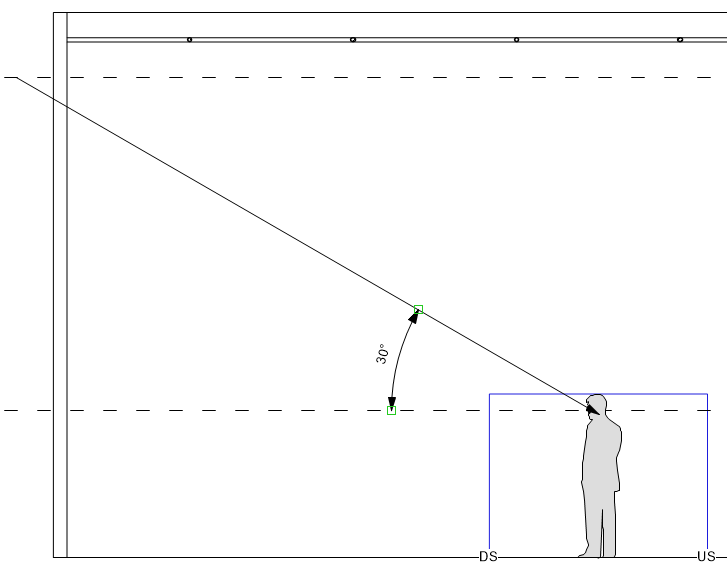
Approach Angle (Side Section View)
|
Options for Front Light Placement
|

Specification for a Taildown
We'll draw this fixture on the plot, but we don't want to make it seem like it is on the same pipe, so we'll draw the actual fixture with the channel number and other data in an alternate location. On the plot, you will see that I have a grey fixture shape in the 'actual' location, along with a local note that calls attention to the taildown. This serves a couple of purposes. First, it signals to the electricians that this fixture is not hanging directly on the grid. Second, it allows us to go in later and hang additional fixtures on the grid pipe above the fixture that we've just plotted if need be.
The beam spread calculation when coming in at a short angle like this is a little tricky. If I go to the top corners of the focus area as we did with the top lights, it makes it look like we need an extremely narrow fixture beam. But you need to remember that the beam also needs to fill in the width of the focus area, so when I'm doing beam calculations on front light especially, I usually use the bottom corner of the front of the focus area rather than the top. This gives me a measurement of 28°, so I'll use a 36° fixture here as well. Add the Channel number and we're done with fixture #2!
In a black box space such as this one, it's easy to add in additional positions like this so that you can get fixtures where you need them. But this technique is also one that you'll use in spaces that have hanging positions at different elevations. You're looking for the position that will give you the closest angle, in order to keep your systems consistent.
In a black box space such as this one, it's easy to add in additional positions like this so that you can get fixtures where you need them. But this technique is also one that you'll use in spaces that have hanging positions at different elevations. You're looking for the position that will give you the closest angle, in order to keep your systems consistent.

|


|
HIGH SIDE LIGHT - Channel (31)
For the next fixture we'll flip our point of view from the Center Line Section (essentially a side view) to the Front Elevation, or Front View of the space. The High Side light wants to come in from a steep angle, 60° up from horizontal, and we'd like the fixtures to be as close to in line with the center of the focus point as possible. Unfortunately, in this situation there is not an 'East/West' pipe available in line with the Focus Area, so I need to rely on the 'North/South' hanging positions. Likewise, when I strike a 60° line up from the Focus Area, I'm almost directly in between two of these pipes, so I need to make the angle steeper or shallower in order to make the shot. If I hang the fixture closer to the Focus Point, I come up with a 72° angle, or 52° if I hang it farther away. I have to think back to the purpose of the light in order to make this decision. I know that the reason that I like this high side light is that it gives me both good visibility on faces in profile, as well as sculpting of body. If I go to the steeper angle, I will likely lose a lot of the benefit of face visibility, because the shadows will be really intense. Therefore, I'll move to the shallower angle (52°). I will still have all that great side light sculpting, but the light will do a better job of lighting faces in profile from this position, so I think this is a good choice to make here.
The beam angle of the fixture is 23°. which is still too wide for me to jump down to a 26° fixture (Beam=18°), so I'll place a 36° fixture in this spot too.
Don't be concerned that it seems like we're using 36° fixtures for everything here. Most venues have an inventory that is appropriate for the photometrics of the space. This space probably has a large number of 36° and 50° fixtures, as well as WFL Flood fixtures. If your space is a large proscenium with 2 or 3 Front of House Catwalks and 30' trims over the stage, the inventory probably has a lot more 10° and 19° fixtures. Trust the geometry, and keep using 36° fixtures where the math says you should.

|

|

Place the fixture on the plot, and label the channel (31) and we're done with another.
DIAGONAL FRONT LIGHT - Channel (41)
Diagonal lights are perhaps the trickiest fixtures to plot using this 2D method of figuring photometrics, because we don't have a natural view that shows us a cross section of the beam. For side light, we can use the front elevation, and for front or back light we use the Center Line Section, but for Diagonal lights we need to make our own section.
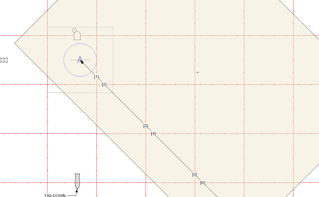
McCandless system diagonal front lights are '45° UP and 45° OVER' - we're kind of looking at 2 different approach angles. 'UP' is the Approach Angle that we've discussed in previous fixtures, and is measured from horizontal, or parallel to the floor. 'OVER' is how 'diagonal' the light is. If we look at the groundplan, this angle is measured from a line parallel to the centerline. For the purposes of this exercise, I'm going to call this the 'Plan Angle'.
To create this auxiliary section view, I'm going to start by laying a sheet of tracing paper over the plot- this gets a little sloppy. I'm going to draw a line along the Plan Angle, starting at the center of the focus point. Every place that the Plan Angle line crosses a hanging position is a possible place for me to hang a fixture. I'm going to mark these 6 possibilities along the Plan Angle line, labeled [1] through [6]. The next step is to figure out which of these spots gives me the closest Approach Angle to 45°.
So here's the confusing leap of faith that makes this work: The Plan Angle that you drew on this sheet of tracing paper is now the floor. I'm going to place a 6' figure standing on the floor directly on the focus point that I can see through the tracing paper. At this point, I can actually take the tracing paper away from the plot, and rotate it so I'm looking at it 'normally', with a horizontal floor. This will help your brain.
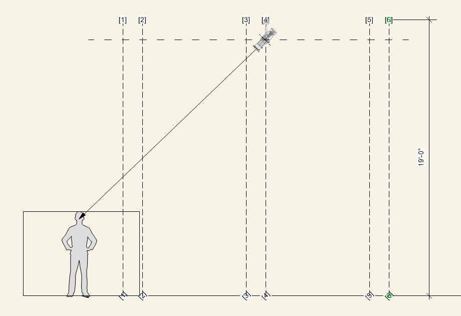
At this point I'll draw the whole focus area rectangle, centered on the figure. We're still working with an 8'x8' focus area, so that's what I'm going to base this on. We know where the Possible Hanging positions are, but the marks are still on the floor. We know that the trim height of the grid is 19', so I'll simply move the hanging position marks up 19' on the page. Remember that the fixture hangs below the grid by a bit, so I'll make the same dashed line that represents where the fixture is in space. Now all you have to do is draw a 45° Approach Angle line from the focus point, and identify the closest hanging position. We'll hang the fixture at hanging option [4].
Diagonal lights are perhaps the trickiest fixtures to plot using this 2D method of figuring photometrics, because we don't have a natural view that shows us a cross section of the beam. For side light, we can use the front elevation, and for front or back light we use the Center Line Section, but for Diagonal lights we need to make our own section.
McCandless system diagonal front lights are '45° UP and 45° OVER' - we're kind of looking at 2 different approach angles. 'UP' is the Approach Angle that we've discussed in previous fixtures, and is measured from horizontal, or parallel to the floor. 'OVER' is how 'diagonal' the light is. If we look at the groundplan, this angle is measured from a line parallel to the centerline. For the purposes of this exercise, I'm going to call this the 'Plan Angle'.
To create this auxiliary section view, I'm going to start by laying a sheet of tracing paper over the plot- this gets a little sloppy. I'm going to draw a line along the Plan Angle, starting at the center of the focus point. Every place that the Plan Angle line crosses a hanging position is a possible place for me to hang a fixture. I'm going to mark these 6 possibilities along the Plan Angle line, labeled [1] through [6]. The next step is to figure out which of these spots gives me the closest Approach Angle to 45°.
So here's the confusing leap of faith that makes this work: The Plan Angle that you drew on this sheet of tracing paper is now the floor. I'm going to place a 6' figure standing on the floor directly on the focus point that I can see through the tracing paper. At this point, I can actually take the tracing paper away from the plot, and rotate it so I'm looking at it 'normally', with a horizontal floor. This will help your brain.
At this point I'll draw the whole focus area rectangle, centered on the figure. We're still working with an 8'x8' focus area, so that's what I'm going to base this on. We know where the Possible Hanging positions are, but the marks are still on the floor. We know that the trim height of the grid is 19', so I'll simply move the hanging position marks up 19' on the page. Remember that the fixture hangs below the grid by a bit, so I'll make the same dashed line that represents where the fixture is in space. Now all you have to do is draw a 45° Approach Angle line from the focus point, and identify the closest hanging position. We'll hang the fixture at hanging option [4].
|
|
Doing a quick calculation gives us an 18° Beam Angle, so for this system we will use a 26° ERS Fixture. These have a single slash in the barrel area. Add the Channel Number (41) and all four of our lighting systems are calculated!

One further note about these calculations. Once you have figured out the Approach Angle, the geometry is repeatable anywhere in the space that has the same trim height. In this Black Box theatre, all the trim heights are 19' (except where we added the taildown). So you already have the information that you need to place a light fixture with a 45° or 60° Approach Angle (and with one additional step, 30°) anywhere in the space. Check out this Section Drawing on which I have composited all 3 of these angles.
Because the grid is 19' everywhere, I know that any fixture that I hang 7'-3" from a focus point will have a 60° Approach Angle no matter what the Plot Angle is! I also know that I measured the Beam Angle for channel (31), and it suggested that I use a 36° fixture to light an 8' area. So I don't actually have to do these calculations every single time from here on out (see, I told you it would get easier!)
Because the grid is 19' everywhere, I know that any fixture that I hang 7'-3" from a focus point will have a 60° Approach Angle no matter what the Plot Angle is! I also know that I measured the Beam Angle for channel (31), and it suggested that I use a 36° fixture to light an 8' area. So I don't actually have to do these calculations every single time from here on out (see, I told you it would get easier!)

From this focus point, using the Plot Distance, any place that the circle intersects a hanging position is a spot where I can hang a fixture and get the same Approach Angle. Now that I've done these calculations once, I can start placing fixtures on the plot really easily, assuming that the focus points are on the stage floor, and the Plot Angle and distance doesn't take me outside of the room. I will continue to have to make compromises as I go along (as we did with the high side light that falls almost exactly between the 30° Approach Angle that I was going for and the 45°) but this will get us close.
On the next page, we'll see what we need to do to expand these four fixtures into complete systems, and also what to do when we put scenery in your way.
On the next page, we'll see what we need to do to expand these four fixtures into complete systems, and also what to do when we put scenery in your way.
BONUS DIAGONAL LIGHT INSTRUCTION:
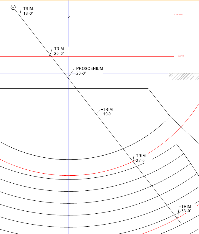
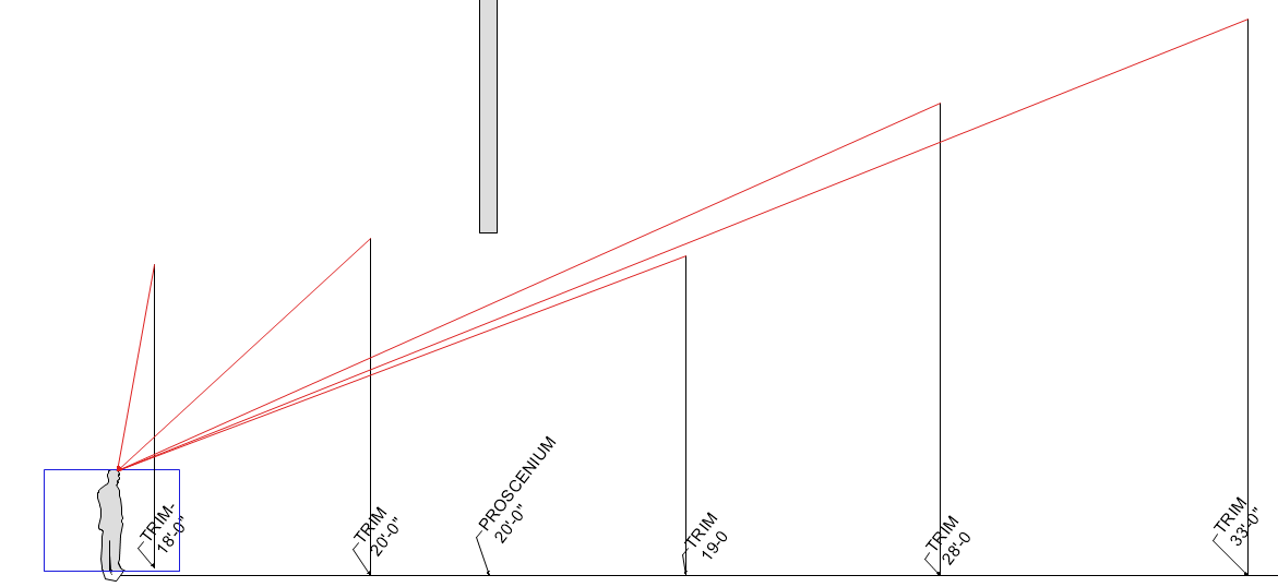
Diagonal lights seem tricky at first, because you don't have a 'built in' view by using the front elevation or the section view to figure out the angles. The example on this page is also probably somewhat inadequate, because in a grid-based space, all of the trim heights are the same, so you can just draw a circle with the correct Plot Distance as the radius, and you're good. However, most of us work in large proscenium spaces, and the trim heights are different. Here is an example using Bush Theatre at CMU as an example. This space has front of house catwalks (which are curved, to make things even more complicated) as well as adjustable battens above the stage.
I can put a random focus point anywhere on the stage, and decide on a random Plot Angle on the plan view drawing. I draw a line along this plot angle. Any intersection with this line and a hanging position is a place that I can hang a light to come in on this diagonal. All I need to do is to measure the plot distance (how far the focus point is from the hanging position) and the trim height (from the floor to the hanging position) and get those points onto a piece of paper. These are the legs of the triangle, and the resulting hypotenuse is the Approach Angle. I can do this from any point on the stage, to any point in the theatre, exactly the same way.
|
|
Notes: All the fixtures here are ETC Conventional (lamp-based) fixtures. The photometric information is published at www.etcconnect.com
