Now that we have plotted a few individual fixtures, the rest of the system goes a little quicker. A system of lights usually shares characteristics like direction and color, and is just placed in a different place on the stage. We've already figured out the geometry for the first fixture, and triangles are triangles- as long as other variables (like trim height or focus point height) haven't changed, then we can simply duplicate that fixture into a different area of the theatre, and we're done.
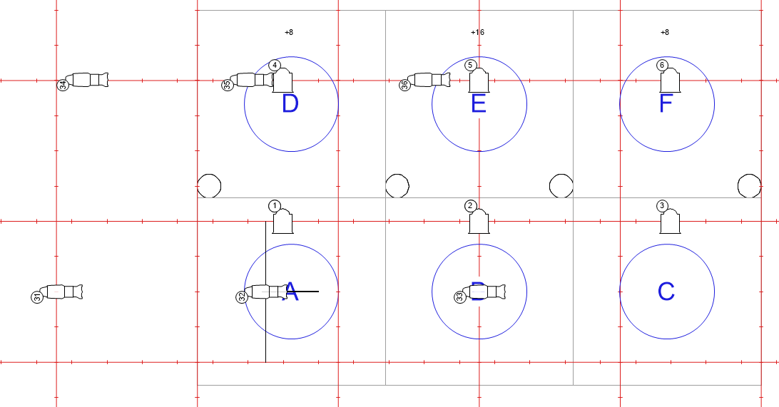
For this example, I have created a very simple scenic layout with 6 equal focus areas. All of the scenic areas are 8' x 8' squares, and the fixtures that we have already plotted are focused into Area A (Down Right). The 3 upstage focus areas are on raised platforms- Area D and Area F are 8" up, and Area E is 16" up. There are also 4 columns along the downstage edge of the upstage areas. In addition, there is a cyc upstage of the set.
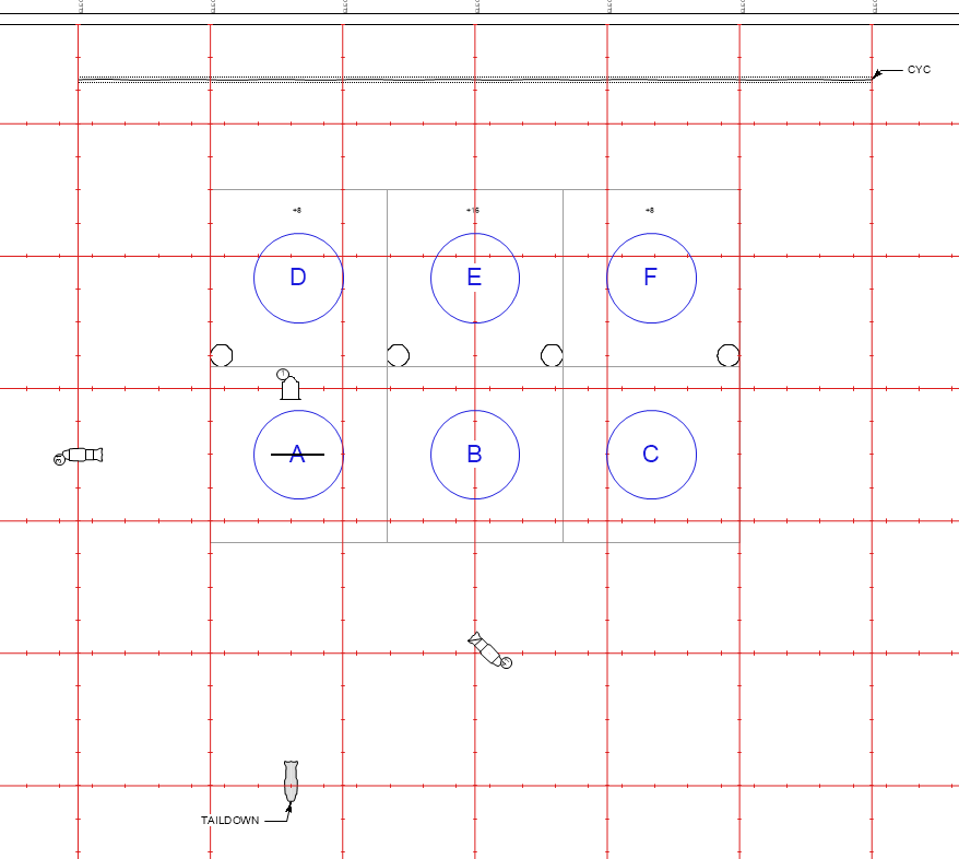
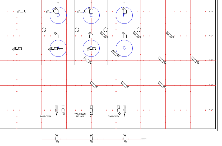
Plan view of the lights we've plotted already and the focus areas
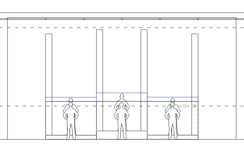
Front Elevation
|

Section view
|
TOP LIGHTS: (1)-(6)
Once again, we will start with the Top light system. This is going to be very simple, based on our previous calculations. Channel (2) and (3) will be placed on the same East/West pipe. The Focus Areas are 8' wide, so we need to duplicate each fixture 8' towards SL.
Looking towards the upstage 3 areas, if we move 8' upstage from (1) through (3), I find that I do not have a pipe. But remember that we compromised somewhat by pushing the angle for (1) to be slightly back. Looking at the location of the pipes for the upstage areas, I can get a truer top light, so that's what I will do. The only factor that would give me pause here would be if the new top light angle were slightly downstage of the center of the focus area. If that were the case, I would have half of the system that was more of a back light, and half that was more of a front light. That would give me vastly different qualities of shadow on faces, so I would probably want to avoid that. However, because, if anything, these fixtures are still a hair upstage of the focus point, so I am OK with the small inconsistency that we've created.
The upstage areas are elevated up off the ground. Because the fixtures are coming straight down, that does nothing to the angle, so we're good there. However, the throw distance is slightly shorter, meaning that the pool of light cast from the 19' trim height will be slightly smaller. I remember that when we plotted the Fresnel fixture for (1), we still had some headroom to zoom the units larger, and the change from 36° to 42° is not going to affect us.

Front Light (11)-(16)
Once again, we have already figured out the geometry for (11), and we just need to duplicate that fixture for Areas B and C. Easy Peasy.
The calculations for Areas D, E, and F will be slightly different. Remember, we decided on a taildown pipe for (11) through (13) because the room wasn't big enough to hang lights on the grid and also make the angle that we were looking for. Because D, E, and F are farther upstage, we have more grid to work with, so we probably do not need to hang a taildown for the upstage areas. Besides the fact that D, E, and F are further upstage, another variable here is that they are raised platforms. D and F are 8" up, and E is 16" up from the stage floor. We will want to take these variations into consideration when plotting the upstage fixtures as well. If that were not enough, the posts in the set will need to be dealt with as well. We will address each of these variables in turn.
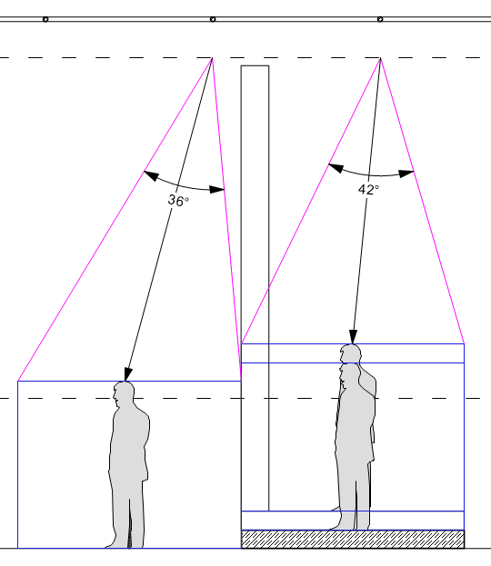
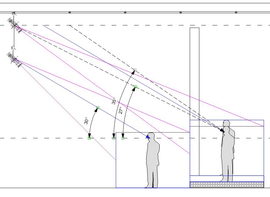
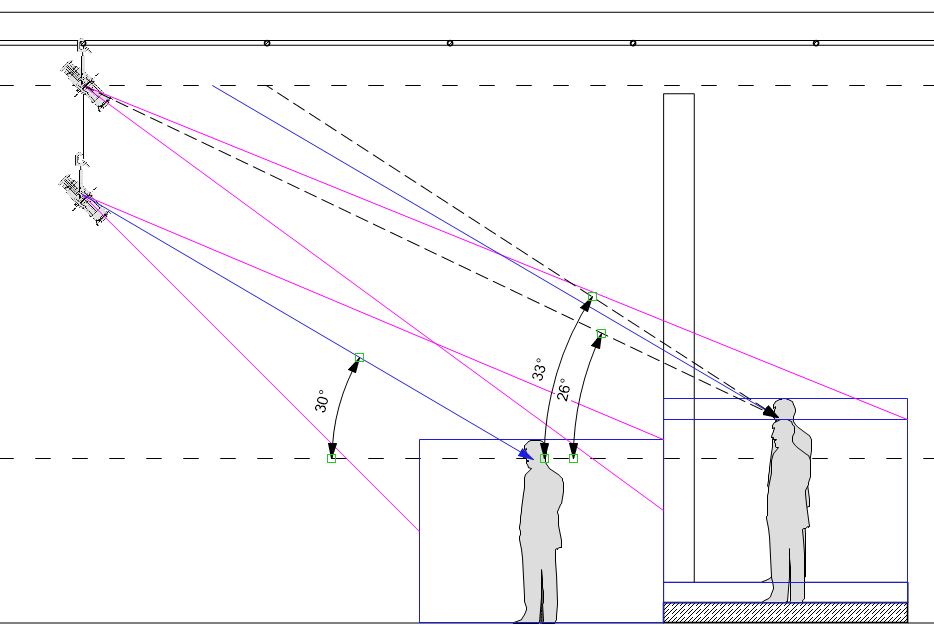
First of all, to figure out the front light angle, we start by duplicating the 30° approach angle from the downstage areas, and instead point it towards the upstage area (rising 8" to account for the platform). This line is for the D and F areas- we'll work with the higher elevation for E later. Once I extend the Approach Angle line, I see, once again, that I'm between pipes, so I will need to either adjust the fixture closer to the focus point (and make a steeper angle than 30°) or farther away from the focus point (resulting in a shallower angle). When I measure these two possibilities, I get a 27° and 35° to choose from. In this case, because the purpose of the system is to fill in as many shadows on the faces as I can, I will go with the shallower angle, and plot the fixtures directly above the fixtures that we used for Areas A and C.
Next, I'm going to check the fixture for the E Area, just to see if the extra 8" makes a big difference. When I move everything up 8", the possible Approach Angles become 26° and 33°. This presents a real dilemma for me. By itself, I would probably push this fixture to 33°, because it's closer to 30°. But once I take the context of the rest of the decisions I've made here into consideration, I'm going to go with the shallower 26° Approach Angle. My reasoning here is that all of the decisions that I've made so far have erred on the shallower side of 30. Additionally, I won't have to readjust my beam angle if I hang the fixture for E the same plot distance as that of D and F, so I won't have to worry about intensity differences later on. But really, if you made the other decision, you're probably going to be OK as well.
Once again, we have already figured out the geometry for (11), and we just need to duplicate that fixture for Areas B and C. Easy Peasy.
The calculations for Areas D, E, and F will be slightly different. Remember, we decided on a taildown pipe for (11) through (13) because the room wasn't big enough to hang lights on the grid and also make the angle that we were looking for. Because D, E, and F are farther upstage, we have more grid to work with, so we probably do not need to hang a taildown for the upstage areas. Besides the fact that D, E, and F are further upstage, another variable here is that they are raised platforms. D and F are 8" up, and E is 16" up from the stage floor. We will want to take these variations into consideration when plotting the upstage fixtures as well. If that were not enough, the posts in the set will need to be dealt with as well. We will address each of these variables in turn.
First of all, to figure out the front light angle, we start by duplicating the 30° approach angle from the downstage areas, and instead point it towards the upstage area (rising 8" to account for the platform). This line is for the D and F areas- we'll work with the higher elevation for E later. Once I extend the Approach Angle line, I see, once again, that I'm between pipes, so I will need to either adjust the fixture closer to the focus point (and make a steeper angle than 30°) or farther away from the focus point (resulting in a shallower angle). When I measure these two possibilities, I get a 27° and 35° to choose from. In this case, because the purpose of the system is to fill in as many shadows on the faces as I can, I will go with the shallower angle, and plot the fixtures directly above the fixtures that we used for Areas A and C.
Next, I'm going to check the fixture for the E Area, just to see if the extra 8" makes a big difference. When I move everything up 8", the possible Approach Angles become 26° and 33°. This presents a real dilemma for me. By itself, I would probably push this fixture to 33°, because it's closer to 30°. But once I take the context of the rest of the decisions I've made here into consideration, I'm going to go with the shallower 26° Approach Angle. My reasoning here is that all of the decisions that I've made so far have erred on the shallower side of 30. Additionally, I won't have to readjust my beam angle if I hang the fixture for E the same plot distance as that of D and F, so I won't have to worry about intensity differences later on. But really, if you made the other decision, you're probably going to be OK as well.
|
|
Next, I want to address the problem of the columns in the downstage corners of the upstage platforms. Because these lights are meant to light people's faces on the platforms, I want to try to make sure that I'm covering as much of those platforms as possible in between the columns. I'm going to look at the plan view to make some minor adjustments to maximize my coverage. If I put the (14) fixture directly above the (11) fixture, and come into the area with a straight ahead Plot Angle (see the pink angle in the image), you'll notice that I lose coverage of the SR edge of the platform. It's not much, but there's a little bit there. Because that post is solid, it's going to be a hard edge also- there's no 'field angle slop' to rely on. I notice that I have a little extra available on the onstage side of the platform though. If I adjust that fixture on slot towards center (blue angle in the image), I gain back those few precious inches on the offstage edge of the platform, without sacrificing any of Area D on the onstage side. So that's what I will do for both (14) and (16) - push them one slot (18") towards center. (15) will stay directly in the middle, because anything I gave to one side of the platform would steal it from the other.
The Taildown note that I placed earlier are now confusing in the center, so I will add a 'BELOW' qualifier here. This will help the electricians understand that this note is not meant for (15).
The Taildown note that I placed earlier are now confusing in the center, so I will add a 'BELOW' qualifier here. This will help the electricians understand that this note is not meant for (15).

A couple more thoughts on this system before we go away:
Now that we've plotted the upstage fixtures, and discovered that the approach angles are 26° and 27°, I could revisit the taildown. We're already doing a custom hanging position that we placed 3'-9" below the grid in order to achieve an exact 30° Approach Angle. I could drop that taildown a couple more inches in order to make the approach angle 27° just like the upstage fixtures, and have a very consistent Approach Angle across the whole system. If I'm doing theatre, I probably don't make this adjustment, but if this is for camera, I would definitely do it. Because of the heightened contrast that is present when using cameras for film or video, this little difference in the quality of the shadows in the different areas might be apparent to the camera.
Secondly, when you're plotting front lights (any lights, really, but especially front lights) you want to be aware of what the spill is going to do on the background. In this case, with these low angle front lights, we almost certainly will see the spill of the front lights on the cyc. Because I've thought through how I am likely to use these fixtures in my show, I'm not that concerned about this. I'm looking to get most of my visibility and shaping from the high side light systems, and intend to use these front lights at low intensity for fill light. That, combined with the use of cyc lighting, will lessen the impact of the spill and the shadow on the cyc.
HIGH SIDE: (21)-(26)
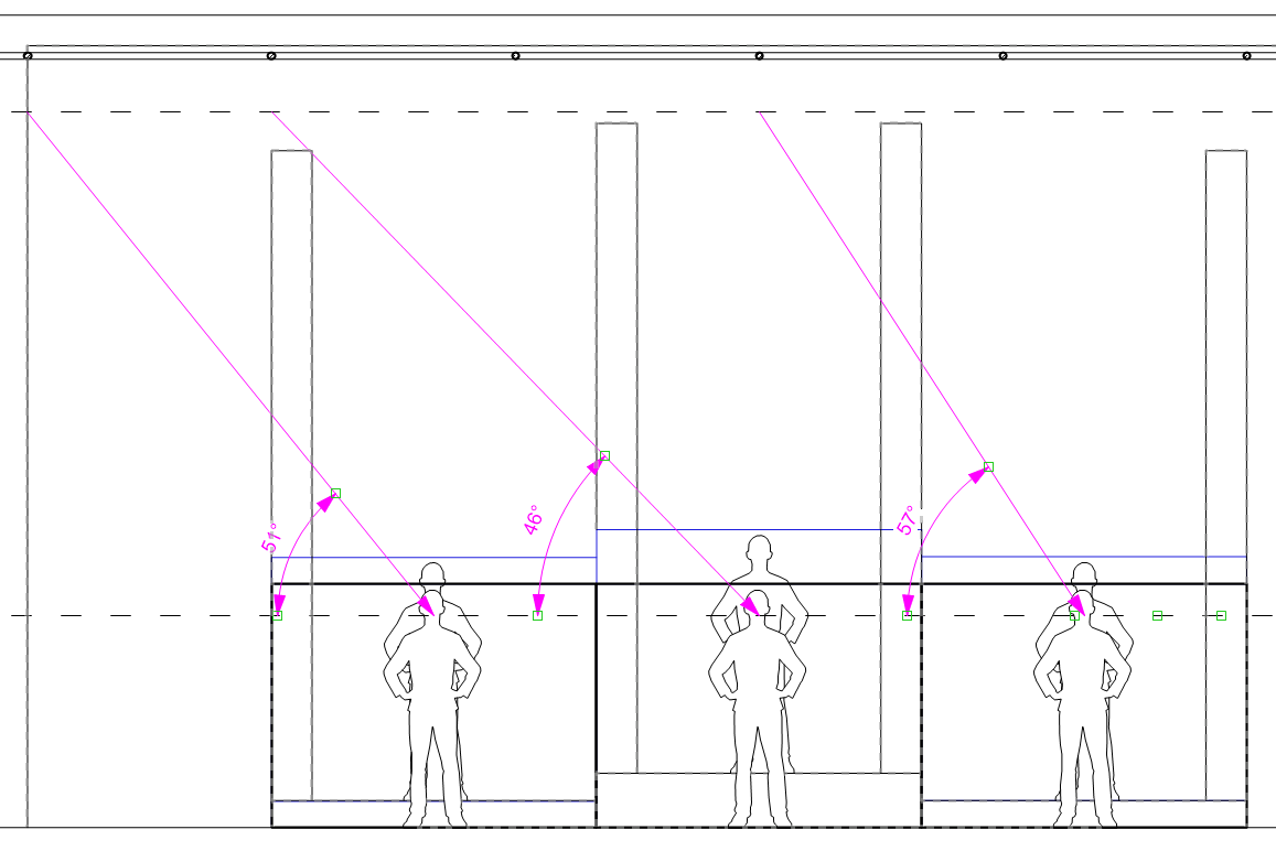
The trickiest thing about extrapolating the geometry on this system is that we are trying to move in 8' increments (the size of the focus area), but the grid has pipes every 6'. This guarantees that there will be no obvious pipe available for the center fixture. I could place the fixtures wherever they land closest to the 60° angle that I'm aiming for, but as you see in the figure below (Option 1), that gives me a wildly inconsistent angle across the three fixtures in the system.
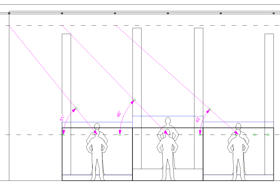
In Option 2, I have the ability to have a slightly more consistent approach, as each angle gets gradually shallower. This is actually a pretty common approach in what we call Pipe-End or Splay systems. In these types of systems, you congregate several light fixtures together (often at the end of a batten, hence 'pipe-end'), and splay the focus across multiple areas. In these systems (in the case of a 3-fixture system), you have a short-throw fixture that is the steepest, a medium-throw fixture, and a long-throw fixture that has the shallowest Approach Angle. You can also build systems that have 5 or 7 fixture arrays. You will also sometimes see an even number system, with the understanding that there is no 'center' area. A system like this gives the illusion that a single light source is lighting the whole alley.
However, in this situation, I know that the angle of the light is important to me, because I want to take the advantage of a 60° high side light to be available for both visibility and sculpting. The 42° Approach Angle for Area C (and even the 46° Approach Angle for Area B) is getting father away from the purpose of the system, so I don't want to compromise this much. So, in this case, I will make a request for a custom pipe to be placed in the gap for the center fixture.
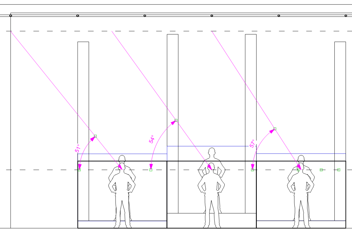
To plot the upstage fixtures, I can use the East/West pipe, so the fixtures can go anywhere. I'm going to choose a consistent angle (not 60°, because we never actually got there on the downstage set). 54° is the middle of the range, so I will get as close as I can to that. I figure out where they go in the front elevation, and then place them on the plot. There are some Fresnels from the top light system in the way of a couple of them, so I'll make some minor adjustments by sliding them slightly offstage, and we're done. Notice that the fixtures aren't exactly in line with the ones for the downstage systems, and that's because we did the Photometrics, and placed the lights where the geometry told us to.
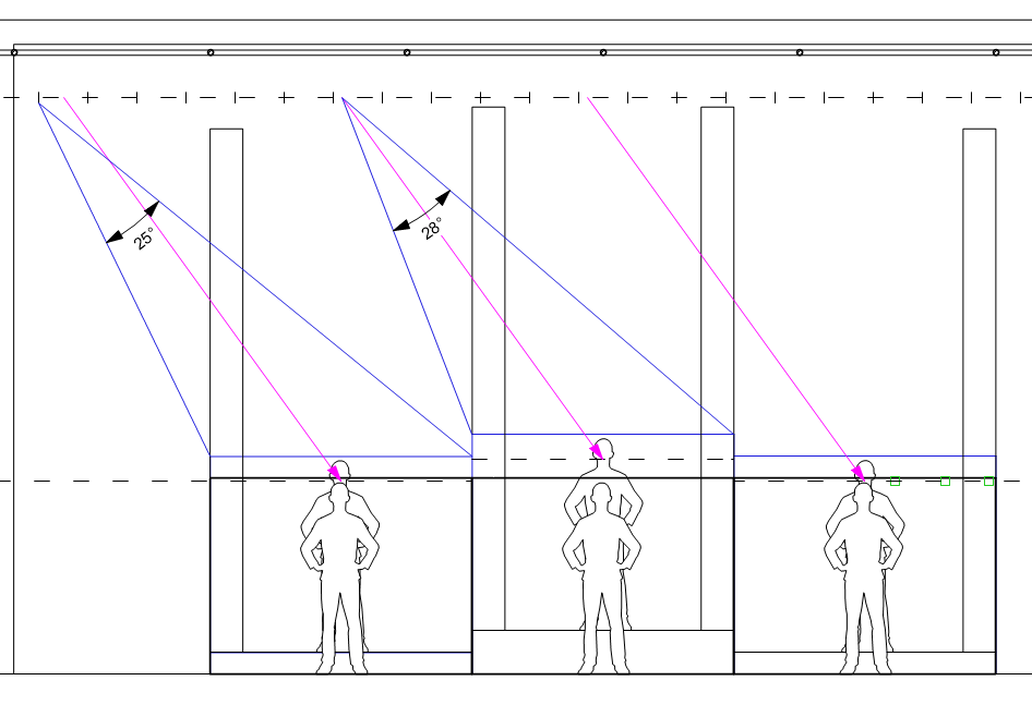
For the downstage fixtures, we'll use the same beam angle as we did for (21), which was a 36°. We want to double-check the beam angle of the upstage units, because we're reducing the Throw Distance. I'll take a measurement here, and see that we're still at 25° and 28°, so a 36° fixture will still be appropriate.
The trickiest thing about extrapolating the geometry on this system is that we are trying to move in 8' increments (the size of the focus area), but the grid has pipes every 6'. This guarantees that there will be no obvious pipe available for the center fixture. I could place the fixtures wherever they land closest to the 60° angle that I'm aiming for, but as you see in the figure below (Option 1), that gives me a wildly inconsistent angle across the three fixtures in the system.
In Option 2, I have the ability to have a slightly more consistent approach, as each angle gets gradually shallower. This is actually a pretty common approach in what we call Pipe-End or Splay systems. In these types of systems, you congregate several light fixtures together (often at the end of a batten, hence 'pipe-end'), and splay the focus across multiple areas. In these systems (in the case of a 3-fixture system), you have a short-throw fixture that is the steepest, a medium-throw fixture, and a long-throw fixture that has the shallowest Approach Angle. You can also build systems that have 5 or 7 fixture arrays. You will also sometimes see an even number system, with the understanding that there is no 'center' area. A system like this gives the illusion that a single light source is lighting the whole alley.
However, in this situation, I know that the angle of the light is important to me, because I want to take the advantage of a 60° high side light to be available for both visibility and sculpting. The 42° Approach Angle for Area C (and even the 46° Approach Angle for Area B) is getting father away from the purpose of the system, so I don't want to compromise this much. So, in this case, I will make a request for a custom pipe to be placed in the gap for the center fixture.
To plot the upstage fixtures, I can use the East/West pipe, so the fixtures can go anywhere. I'm going to choose a consistent angle (not 60°, because we never actually got there on the downstage set). 54° is the middle of the range, so I will get as close as I can to that. I figure out where they go in the front elevation, and then place them on the plot. There are some Fresnels from the top light system in the way of a couple of them, so I'll make some minor adjustments by sliding them slightly offstage, and we're done. Notice that the fixtures aren't exactly in line with the ones for the downstage systems, and that's because we did the Photometrics, and placed the lights where the geometry told us to.
For the downstage fixtures, we'll use the same beam angle as we did for (21), which was a 36°. We want to double-check the beam angle of the upstage units, because we're reducing the Throw Distance. I'll take a measurement here, and see that we're still at 25° and 28°, so a 36° fixture will still be appropriate.
Option 1: As close to 60° without going over as possible
|
Option 2: Moving towards a 'splay' system architecture
|
Option 3, adding a position for area B
|
Angles for the upstage Areas
|

DIAGONAL FRONT LIGHTS (41)-(46)
Once again, the downstage series of fixtures is relatively easy. (41) is already on an 'East/West' pipe, so I'll duplicate that as close to 8' and 16' towards SL as I can for (42) and (43). The real complication comes when I try to plot the Upstage fixtures. Look at the figure that shows what happens if I hang a fixture for Area E at the same angle as for Area B. The scenic post gets in the way and casts a major shadow across much of the center of the focus area! If I Shutter inside of the post, I leave much of the upstage edge of the area uncovered. So, I have some decisions to make, and those decisions are completely based on my planned usage for the system. In this hypothetical, we don't actually have a play to work with, because these were really just systems to illustrate how to go through the mechanics of plotting, but in a real design, here are some of the options that I would see as solutions:
Once again, the downstage series of fixtures is relatively easy. (41) is already on an 'East/West' pipe, so I'll duplicate that as close to 8' and 16' towards SL as I can for (42) and (43). The real complication comes when I try to plot the Upstage fixtures. Look at the figure that shows what happens if I hang a fixture for Area E at the same angle as for Area B. The scenic post gets in the way and casts a major shadow across much of the center of the focus area! If I Shutter inside of the post, I leave much of the upstage edge of the area uncovered. So, I have some decisions to make, and those decisions are completely based on my planned usage for the system. In this hypothetical, we don't actually have a play to work with, because these were really just systems to illustrate how to go through the mechanics of plotting, but in a real design, here are some of the options that I would see as solutions:
- How important is it to repeat this system in the upstage areas? Because the scenery is different, it's possible that the way we use the diagonal front lights downstage might be different than upstage. Maybe we can turn this into a 3-fixture system.
- If it is important to keep, perhaps we can add a second fixture to the area to fill in the other side of the post.
- If the purpose of the system allows it, maybe the upstage fixtures can be more of a side light than a diagonal front light. This is probably true if the system is more of an environmental system than an Area Light system- is this primarily for visibility? If so, then making it a side light may not be an appropriate choice, but if it is a system that adds color or texture to the scene to help set the given circumstances or mood, maybe swinging the angle of the upstage fixtures is an appropriate choice.
- Following up on the previous note, I might find that I want to change the angle of ALL of the fixtures in the system- maybe I decide at this point that the diagonal front light angle is the least important characteristic of the system, and all of them can be turned into side lights. This is an example of the fluid nature of lighting design. As you add variables to the design, it helps to drive your decisions, and motivates revisions.
|
For the purposes of this tutorial, I will plot option #2: Adding an additional fill fixture to each of the upstage areas, so that I can cover the whole area without losing the integrity of the directional system.
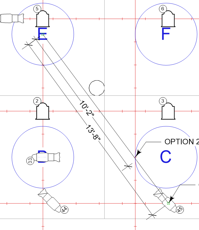
In order to do this, I will start by plotting three fixtures simply by duplicating, as close as I can, the Plot Angle upstage. Let's check the Approach Angle by creating a custom section. The Plot Angle crosses hanging positions at 10'-2 and 13'-8". We'll make a section view with these two plot distances to see which gets us closer to a 45° Approach Angle. We can clearly see from this drawing that due to the 16" platform in the Focus Area, the 10'-2" Plot Distance is the appropriate placement. I'll place the first fixture (we'll call it (45)A, but eventually these two fixtures will both be simply channeled as (45)), and sketch out how much light I can get between the posts. Now I want to find a spot on the other side of the post that will do all of the following:
The first thing I'm going to do in order to make life a little easier is to move the first fixture Downstage 18". I'm concerned that the shadow of this primary fixture is going right across the center of the focus area, and by flattening out the Plot Angle a little bit, I gain more of the area in the first place. Second, I'll draw an arc with a 10'-2" radius to see what my possibilities are for the second fill fixture. It looks like the best placement might be right where (3) is hanging, but we don't want to move that fixture, so I'm going to push (45)B either onstage or offstage. If I go onstage, I still have a pretty significant dark spot in the Focus Area that I can't cover with either light because of the post. So I'm going to push it further offstage, make it more of a side light, and we'll see that the dark spot is significantly diminished, so this looks like the right choice. I'll take a measure of the angle in the plan view to determine the beam angle required for each fixture. The 28° measure of the main fixture leads me to a 36° fixture. The Fill fixture requires a larger beam angle, so I'll plot a 50° for that one. In this case I'm going to include both of these fixtures in the same control channel (45). I've determined that the two lights will always act as one, and will be at the same level at every moment in the show. If I decided that I needed more specific control over each of the lights in the pair, I would need to give the fills a unique channel number. In this case, I, or a console programmer, will need to calibrate the brightness of the two fixtures inside the patch by profiling the dimmer level. This is a process to make sure that the two fixtures have the same apparent brightness on stage. The fill fixture is a 50°, and therefore will probably be a bit dimmer than the 36° that we are using for the main fixture. Once the fixtures are hung in the space, we can profile the dimmer for the main fixture until the two fixtures appear to have the same brightness. If the 36° looks the same at 80% as the 50° does at 100%, then the dimmer profile simply proportions the brighter instrument down. Now that all of the decision making is finished, I can go through the process again for Area D and Area F, and all four of our systems are plotted! |
Find the possible hanging locations and measure the Plot Distances
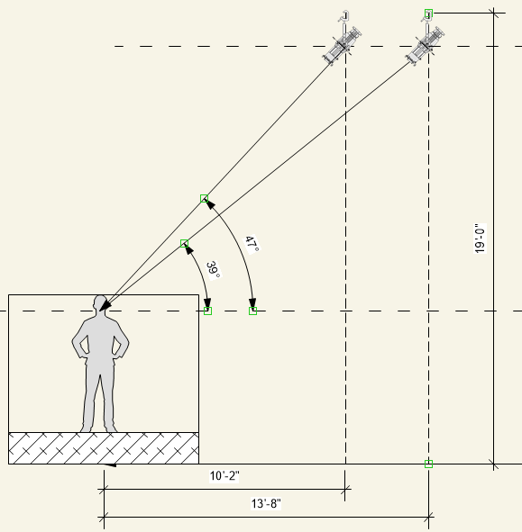
Create a section and determine the Approach Angle
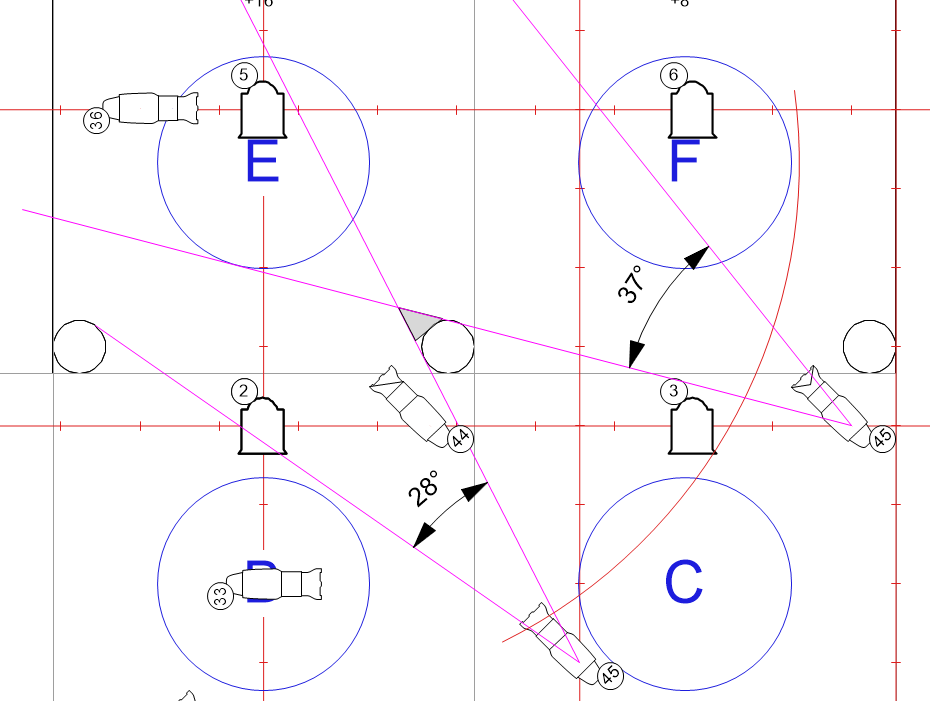
Add a second fixture and measure the beam angles to determine the proper fixture to use.
|